The Best Fluffy Pancakes recipe you will fall in love with. Full of tips and tricks to help you make the best pancakes.
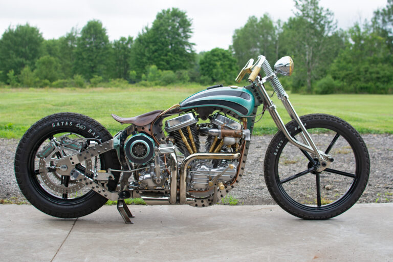
This is part of a build series focused on reproducing a Harley Davidson JD frame using 3D metal printed components combined with traditional frame fabrication techniques.
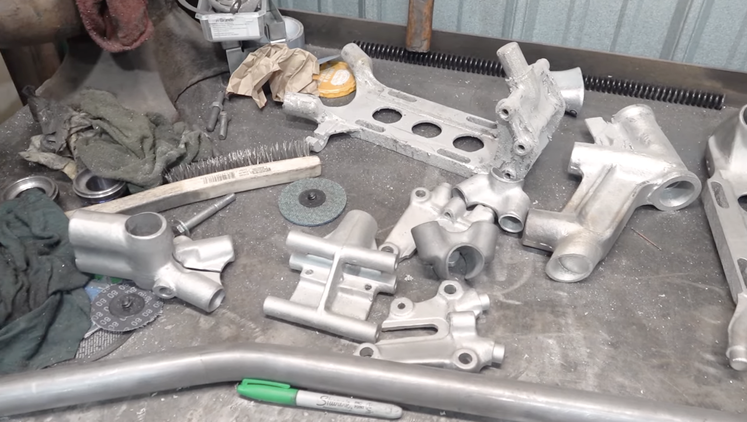
In this post, I am walking through the printed frame components, the post processing required to make them usable, and the early mockup process before final alignment and welding.
Printing the Frame Castings
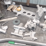
The core structural castings for this JD frame are produced using metal additive manufacturing. These include the frame neck, transmission casting, seat post mount, rear axle plates, and rear fender mount frame brace.
Once printing is complete, the parts are removed from the build plate and prepared for post processing. At this stage, the parts are fully formed but still covered in support material that must be removed before they can be used in the frame.
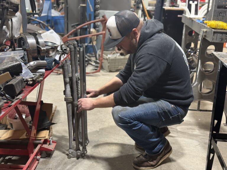
Post Processing and Support Removal
Before removing supports, the parts are soaked with water to reduce airborne dust during cleanup. The support material system we use is designed to provide stability during printing while still allowing for efficient removal afterward.
Most of the lattice style support material can be removed by hand with minimal effort. Larger or more complex areas are secured in a vise and cleaned up using hand tools or air tools depending on the size and shape of the part.
Some areas of the print include small cylindrical features that act as heat sinks during the printing process. These help control heat and prevent distortion as the part is built. Once printing is complete, they are removed as part of the normal cleanup process.
This stage moves quickly. In most cases, all support material can be removed in ten to fifteen minutes per part.
Integrated Features and Threaded Details
Many functional features are built directly into the printed components. Reliefs, contours, and threaded holes are formed during printing rather than added later.
Threads are printed to size and only require chasing with a tap to clean them up. There is no need to cut threads from scratch, which helps maintain accuracy and saves time while keeping everything consistent with the original design.
After support removal, small burrs and edges are cleaned up using tools. The parts are then vapor honed to even out the surface and prepare them for assembly.
Mocking the Frame
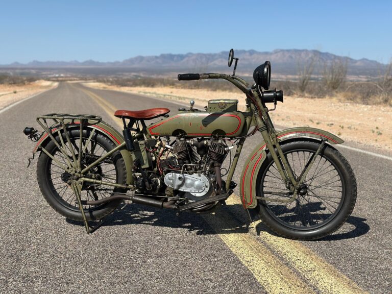
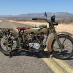
With the castings cleaned and finished, the frame is mocked up in a fixture using measurements taken directly from an original 1920 JD frame. Some of the tubing has already been bent, with additional bends to be completed in the next phase of the build.
The printed castings are fitted to the tubing to establish the basic structure of the frame. At this stage, everything is assembled loosely to confirm fit and geometry before final alignment.
Alignment and Geometry
Once mocked up, the frame is checked for straightness and symmetry. A centerline is established along the backbone, and alignment is verified from front to back and side to side.
Many original frames have developed twists or alignment issues after decades of use. This process allows us to correct those issues while preserving the original geometry and proportions of the JD frame.
Rear axle plate positioning is based on reference points taken from the original frame. Final alignment ensures the frame is straighter than most factory originals while remaining visually and dimensionally correct.
Next Steps
The second part of this series will cover final tube bending, including the rear frame legs, installation of the engine cradle loops, and full fixture setup prior to welding.
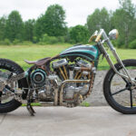
This frame is being built for real use and will be ridden thousands of miles. One of the frames currently under construction is scheduled to take part in the Motorcycle TransAm, covering approximately four thousand miles from coast to coast.
This is the kind of testing these frames are built for.